Home
About VSI
What We Do
Who We Are
Contact Info
Resources
Blog
Data Archives Export
Photo-voltaic Power Generation System
Installation
Preliminary Preparation
The PV installer, Aurora Energy, has made two site visits, one with the excavation and concrete subcontractor, to assess the site in preparation for installation beginning in early September. The rough locations of the eight concrete piers to support the ground mount system have been placed:
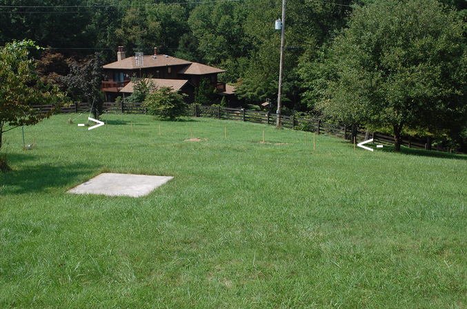
The stakes don't show up very clearly in this photo; the eastmost and westmost stakes are shown with white arrows. The ground mount structure will extend 66 feet in the east-west direction, and about 16 feet north-south.
The piers will be 24" in diameter and must extend at least 6'-6" (80 inches) below grade. Since the site slopes almost 4 feet along the 66' extent of the ground mount structure the piers will have varying heights above grade, from about 6 inches at the east end to roughly 4 feet at the west end.
Some expensive panels and inverters may be residing at the site unattached for a brief period, and will exposed to determined thieves permanently, so a motion sensing surveillance camera was installed to monitor the site:
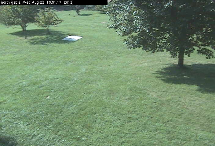
Alas, the oak tree obscuring the upper right portion of that view will need to be cut down as it will shade the panels.
A search of the and Frederick County permits shows that the electrical and building permits have been obtained.
Interior Wiring
On Thursday the 13th and Friday the 14th of September Aurora began work on mounting the Xantrex
hybrid inverter indoors. The Aurora electrician, Homer, elected to use EMT (thin wall metal)
conduit for the interior wiring runs. That is the optimum approach in my opinion; more trouble
initially but pulling the wires once all the conduit is in will be a breeze. Homer and his colleagues
did a first class job of snaking the conduit through and around the existing plumbing and wiring:
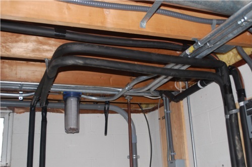
In the right-hand shot the conduit that will lead to the tranfer switch (darker grey box to the
far right) is not connected yet, as that would require disconnecting the power to the switch which
would mean we would lose the ability to run the backup generator.
Note there will be a total of five conductor runs to those existing three boxes: one interactive inverter and the load side of the Xantrex (Schneider Electric) hybrid inverter to the critical loads panel (leftmost box), the other interactive inverter and the line side of the Xantrex hybrid inverter to the service entrance (middle box), and a line from the generator to the Xantrex hybrid inverter (rightmost box). The transfer switch will lose its original function of switching between grid and generator power, instead it will be used to switch between the current generator and a second diesel generator we may eventually acquire.
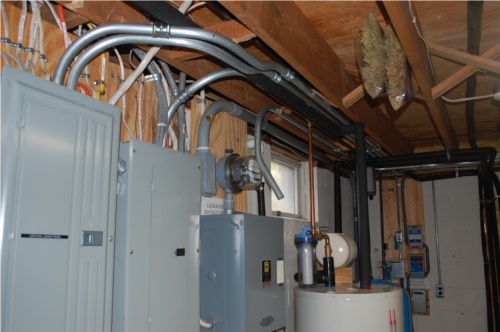
The Aurora crew also mounted the Xantrex XW hybrid inverter on a piece of 3/4" plywood fastened to the basement wall:
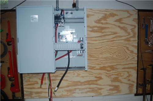
Note the heavy (4/0 gage) cables for the battery. That initially struck me as overkill for a system that
will nominally draw less than 100 amps, but a query to Xantrex and some research showed that the
inverter is capable of a sustaining a short term 200% surge and the DC circuit breaker is sized
accordingly at 250A.
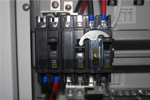
Note the Xantrex power distribution panel has a clever design to allow bypassing the inverter entirely using three double pole circuit breakers.
The breaker on the left protects the line (grid) side. The breaker on the right protects the load side. The breaker in the middle parallels the line side breaker on the topmost side and the load side breaker on the load side. A mechanical interlock mechanism prevents both the center and right hand breakers from being closed at the same time. In normal use the center breaker will be open and the right hand (load side) breaker closed. To bypass the inverter the right hand breaker is opened and the center breaker is closed.
These three factory supplied breakers are 60A. We will have to backfeed the service entrance (line side) with a 50A breaker because of the 120% rule (NEC article 705.12(D)(2)) that limits the sum of all backfeed and main breakers to 120% of the bussbar rating. The bussbar is 200A and the main breaker is 150A, leaving 90A total for the interactive inverter backfeed (40A) and the hybrid inverter backfeed (50A).
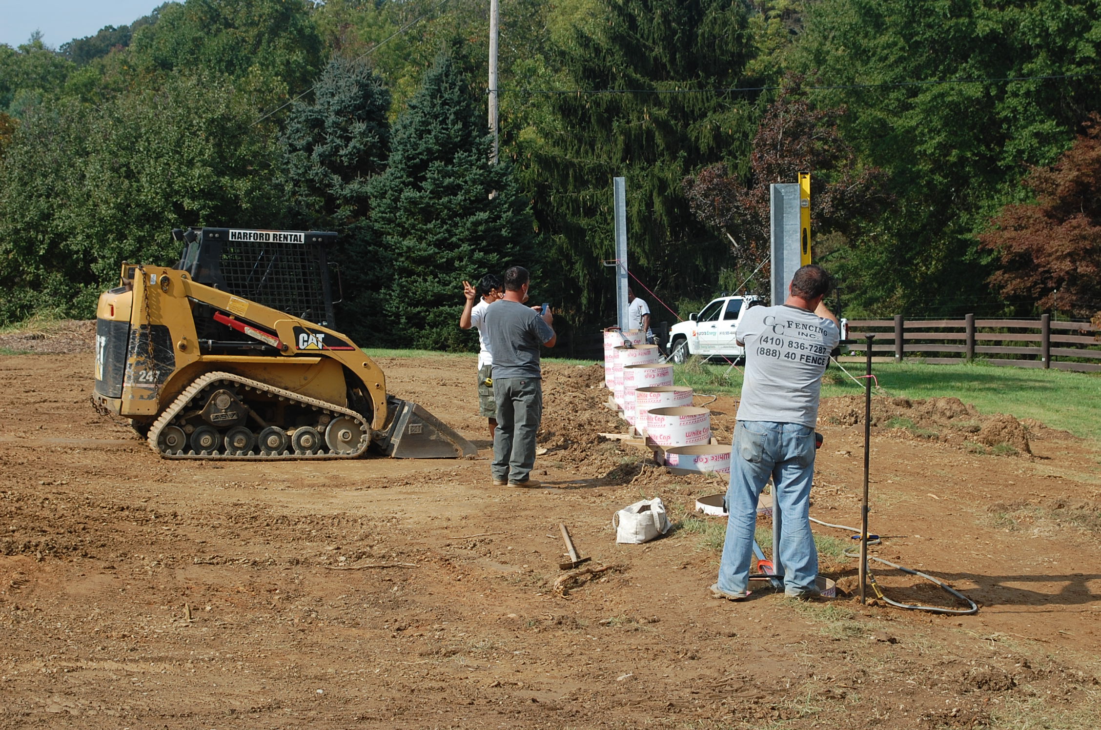
Excavation and Concrete
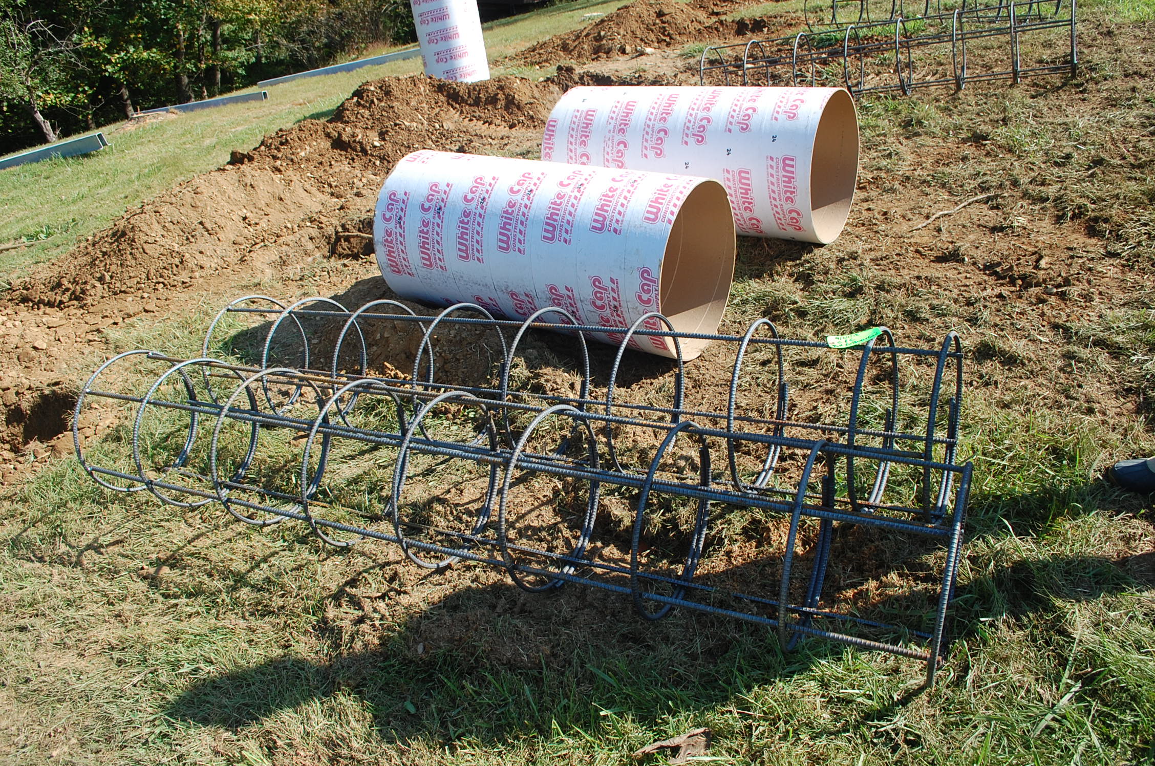
On September 25th the eight holes for the concrete piers were bored and the Sonotube and rebar
cages placed. The prime contractor, Aurora Energy, subcontracted
C&C Fencing of Bel Air Maryland to assist with the
excavation and concrete work. At first thought the
use of a fencing contractor seems odd, but as the work progressed it became clear that placing the
eight vertical metal supports was a lot like erecting a fence.
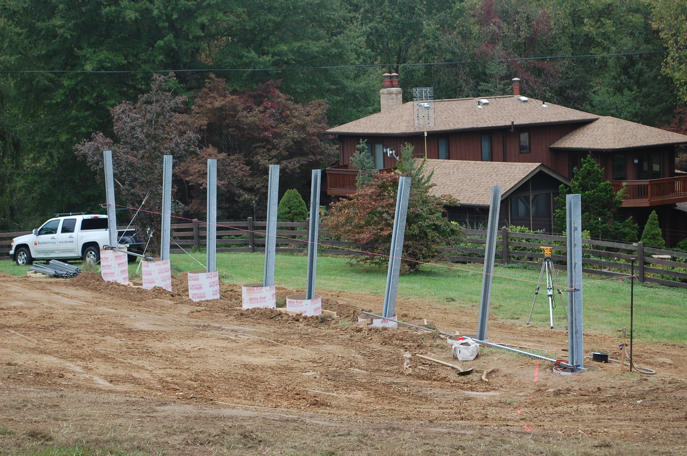
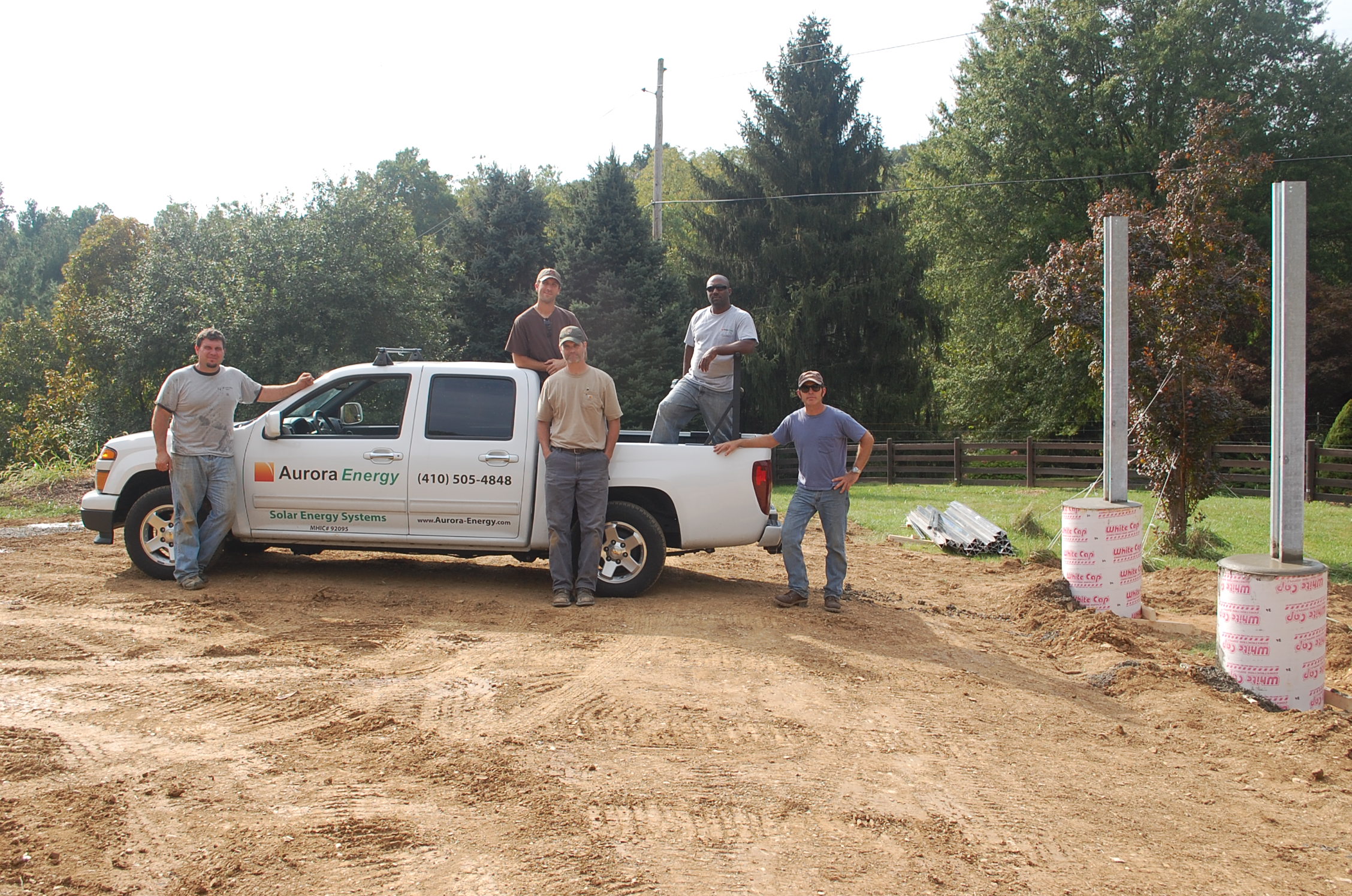
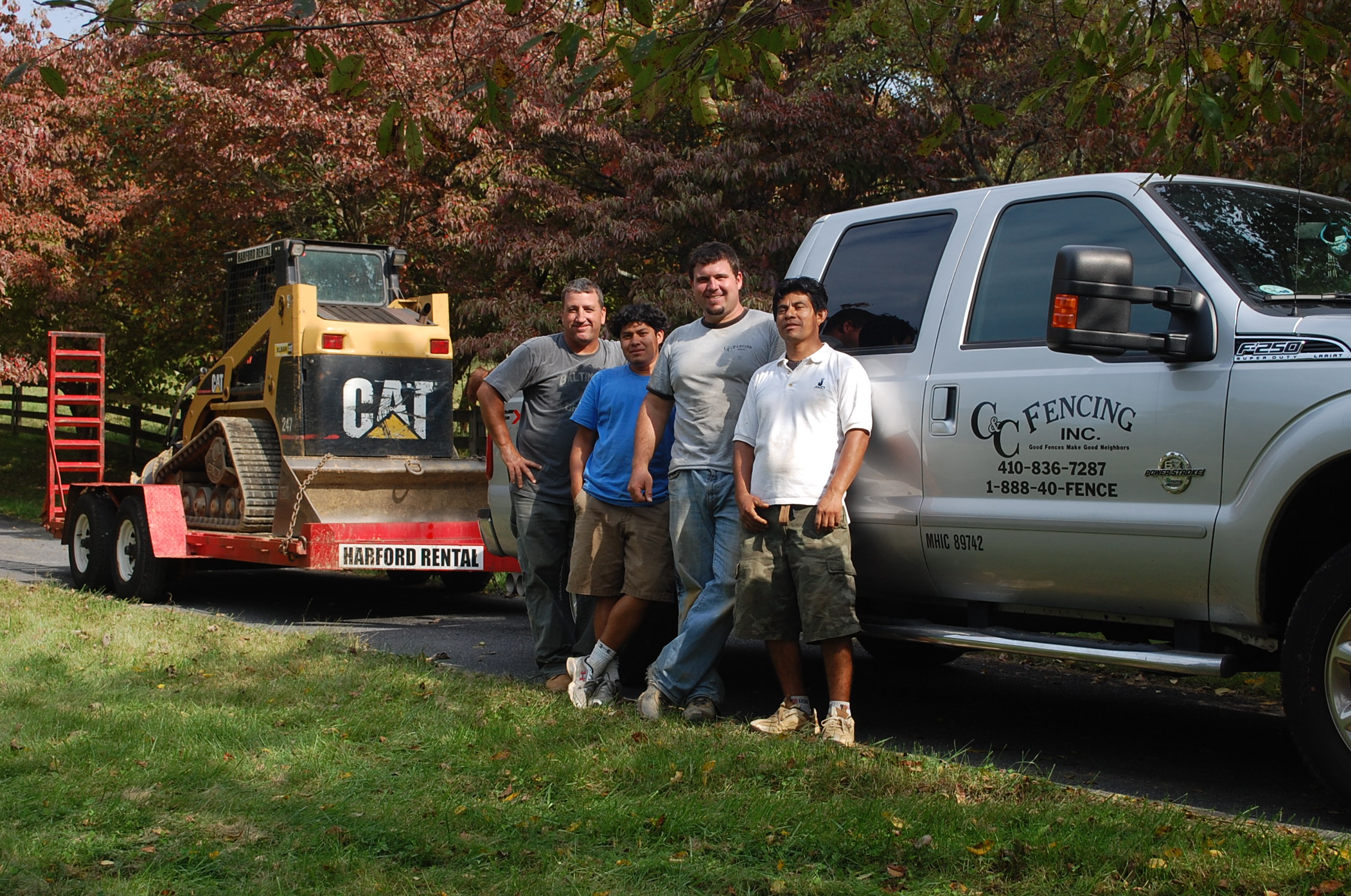
Some shots of the work in progress:
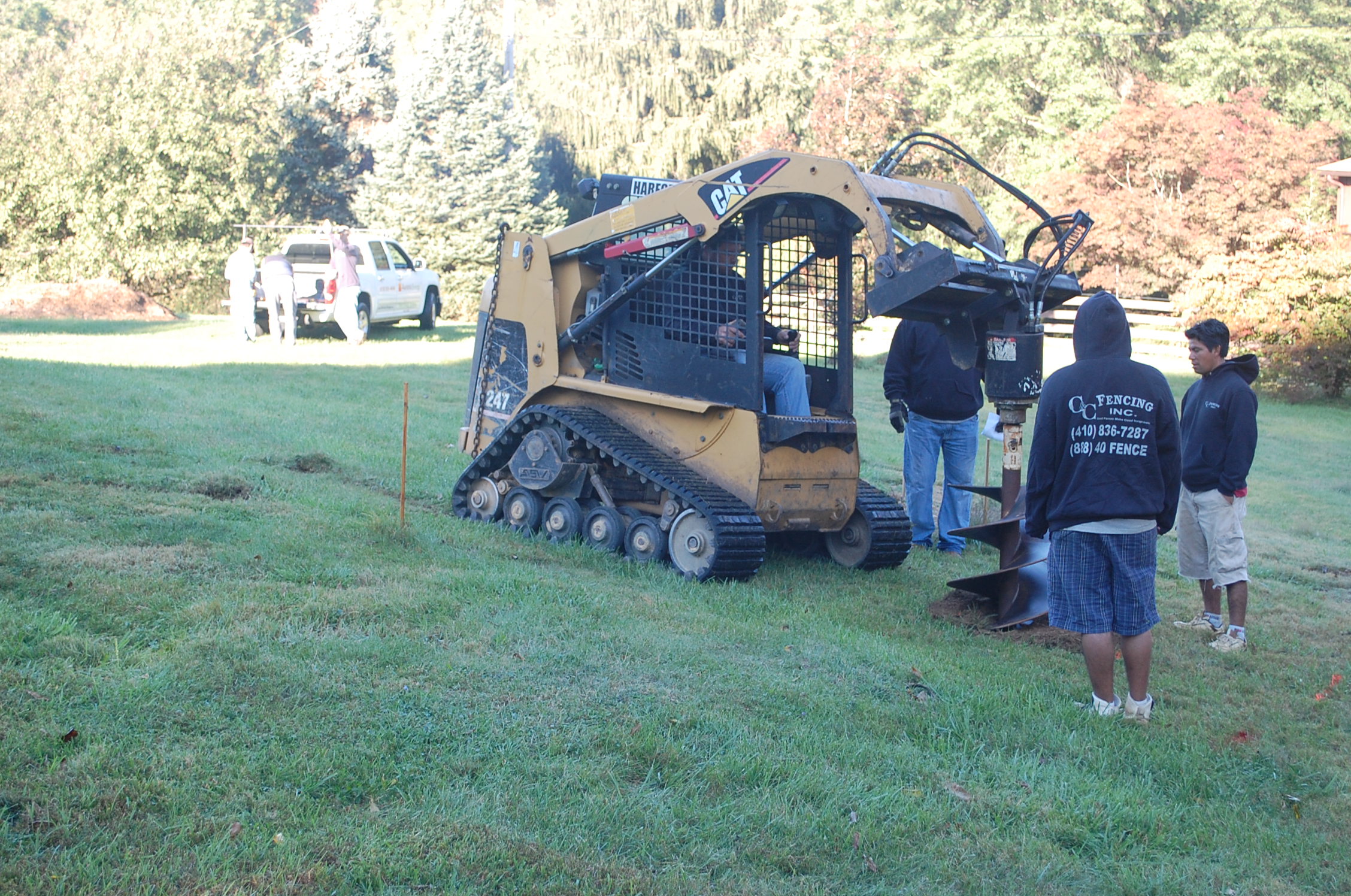
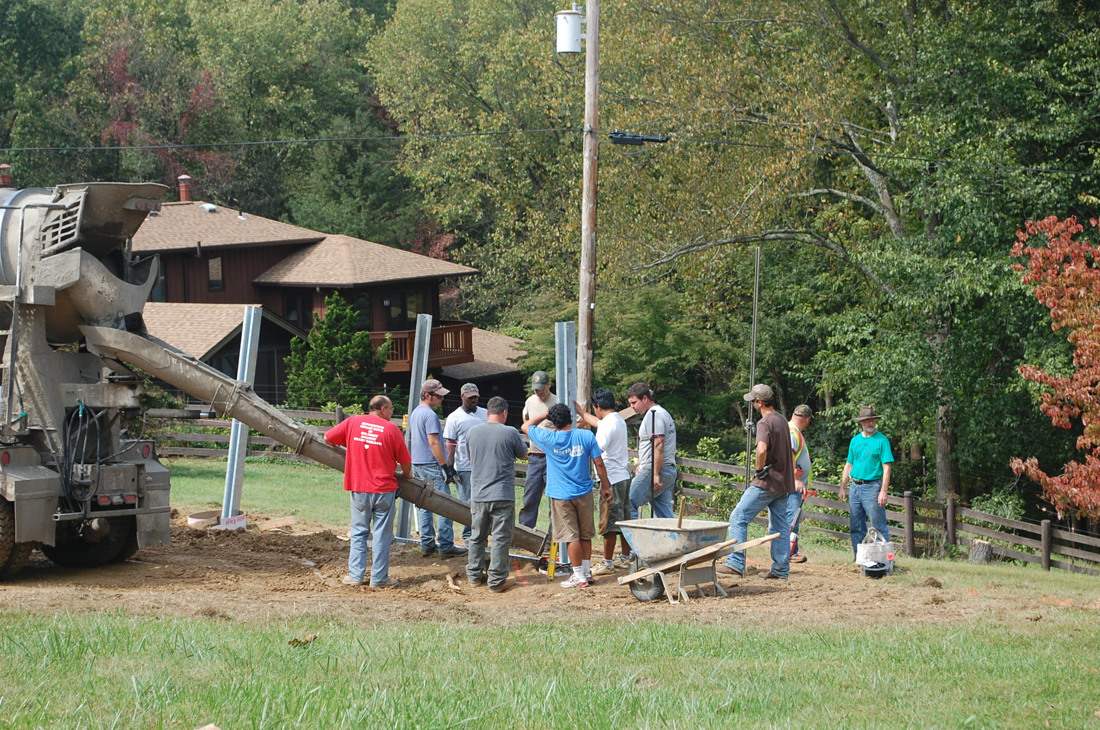
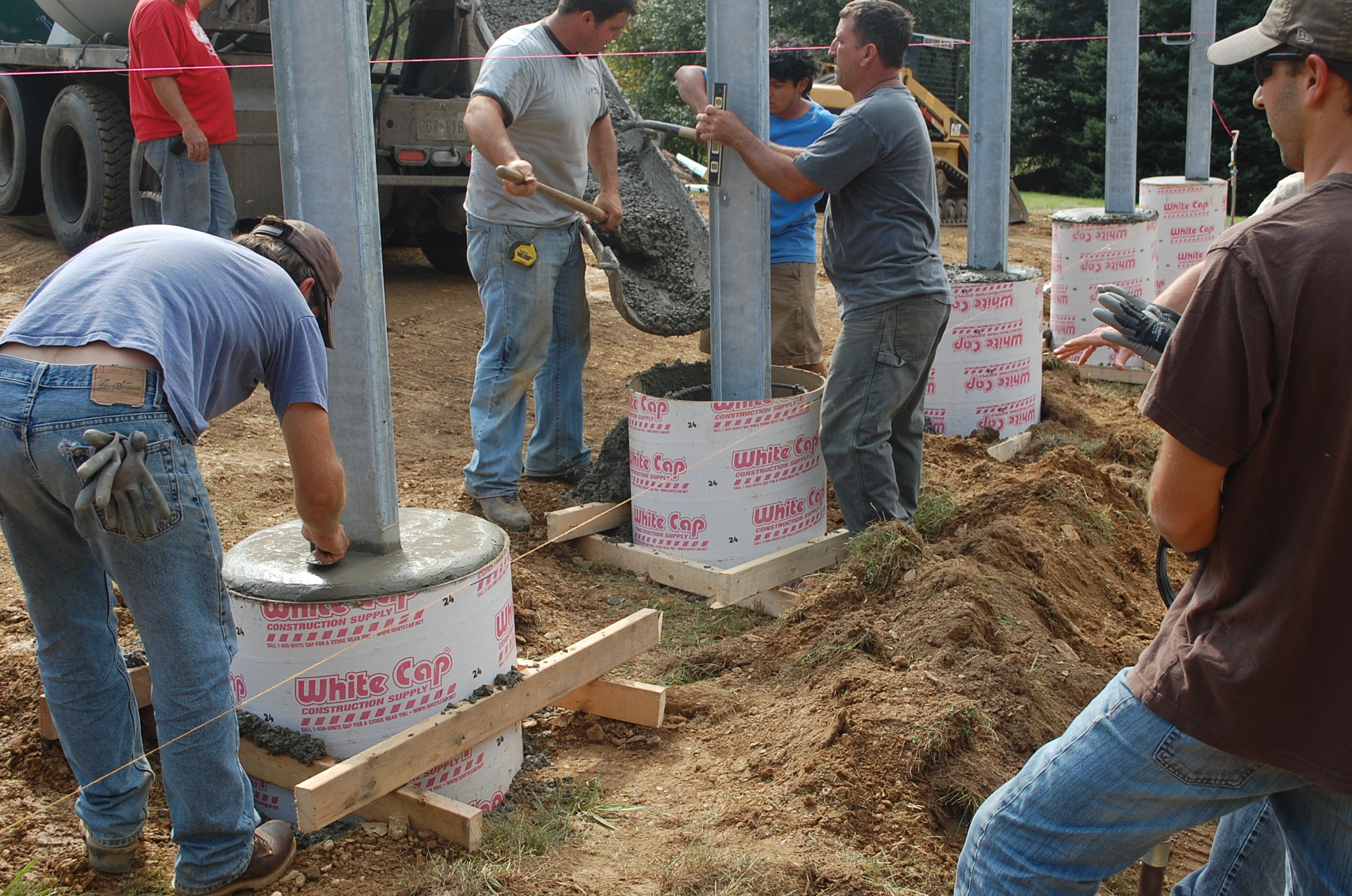
The Aurora crew after a hard days work installing the support piers. The C&C Fencing crew at the end of the same day.
The piers turned out to be a little lower than planned because we were unable to regrade the
terrain as much as we'd hoped, due to the multiple buried phone, power, and water lines to the
east. Jason of Aurora later figured out an elegant solution by obtaining bolt-on extensions from
the manufacturer of the mounting system,
Schettler, Inc., to extend the verticial galvanized steel
posts an additional 16 inches.
|
This site Copyright © 2002-2016 VSI. |